Quantcast
Channel: The ANSI Blog
Viewing all 2061 articles
Browse latest View live

ANSI/PLASTICS B151.1-2017 - Safety Requirements for Injection Molding Machines

$
0
0

ANSI PLASTICS B151.1 2017 Injection Molding Machines Safety


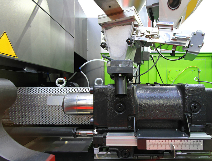
The global market for injection molding, the process of injecting molten plastic materials into a mold before solidifying them, was valued at $199.88 billion in 2014, and it’s projected to grow in the near future. The use of injection molding machines (IMMs) is one of the primary methods utilized for meeting plastic demands, and it serves various end-use industries, such as packaging, automotive, electrical & electronics, home appliances, and medical devices. Improvements in safety and recent innovations that minimize the rate of faulty production have enhanced the significance of IMM technology.

ANSI/PLASTICS B151.1-2017 - Plastics Machinery - Safety Requirements for Injection Molding Machines is an American National Standard that focuses on the safe use of Horizontal Clamp Injection Molding Machines (HCIMMs) and Vertical Clamp Injection Molding Machines (VCIMMs) that process plastic materials and inject them into a mold held closed by the acting clamp. The main difference between these two IMM types is the orientation of the clamping mechanism to the molds, but the safety considerations for identifying and addressing hazards are identical.

According to the standard, there are several parties responsible for identifying and addressing risk in IMMs, depending on the state of the machines. For existing IMMs, the user is responsible for addressing operation hazards associated with installation, set-up, operation, and maintenance. For those being manufactured, repaired, or modified, the responsibility is either shared or split between the user and the supplier.

ANSI/PLASTICS B151.1-2017 also lists and details the many hazards present in injection molding machines. Each component of these machines, including the mold area, clamping mechanism area, area of movement of core and ejector drive mechanisms, nozzle area, injection unit area(s), feed opening area(s), area of the heater(s) of the injection cylinders, parts discharge area, and hoses, can introduce hazards to personnel. These hazards can be either mechanical or thermal, exposing workers to potential burning, crushing, shearing, or other impacting threats.

Understanding the IMM temperature or movement-based hazards discussed in ANSI/PLASTICS B151.1-2017 and implementing the appropriate risk reduction measures can assure personnel safety.


ANSI PLASTICS B151.1 2017 Injection Molding Machines Safety


ANSI/PLASTICS B151.1-2017 is a revision of the American National Standard ANSI/SPI B151.1-2007 - Safety Requirements for the Manufacture, Care, and Use of Horizontal Clamp Injection Molding Machines, and it has also been combined with ANSI/SPI B151.29-2014 - Safety Requirements for Vertical Clamp Injection Molding Machines, replacing both documents. Due to this inclusion, the current edition is able to provide safety guidelines for both horizontal and vertical clamp IMMs.

Additional changes to the revision include the optional use of a mechanical device on horizontal clamp IMMs, safety interlocks are no longer exclusively done by the position sensors but other non-contact, the modification of some paragraphs for clarity and intent, the addition of some electrical requirements, added illustrations, alterations of paragraphs to conform more closely to changes in technology, the addition of risk reduction measures, and updates to Motion/No Motion option for platen core and ejectors movement, among others.

ANSI/PLASTICS B151.1-2017 - Plastics Machinery - Safety Requirements for Injection Molding Machines is available on the ANSI Webstore.

Sanitation in Places of Employment

$
0
0

Sanitation Places of Employment ANSI PSAI Z4.1 2016


Places of employment are one of the foremost settings in the average individual’s life. Due to their significance, it is essential that these venues remain safe for personnel in many conceivable ways. Among the multitude of safety issues that employers and those involved with building design must consider, sanitation is unquestionably a must-have, as it is one of the main requirements for living a healthy life.

However, defining sanitation can be a challenge, and different sanitation concerns may take precedent over others. According to ANSI/PSAI Z4.1-2016 - Sanitation - In Places of Employment - Minimum Requirements, a sanitary condition is “that physical condition of working quarters which will tend to prevent the incidence and spread of disease.” The different means of achieving a sanitary condition for a workplace are detailed in this standard.

ANSI/PSAI Z4.1-2016 covers the guidelines for sanitation in all places of employment except: where domestic, mining or common carrier transportation work only is performed, temporary employment locations, or places where non-sewered waste disposal systems are in use.

The places of employment sanitation guidelines consider the following:

Housekeeping and Waste Disposal


For a sanitary work environment, ANSI/PSAI Z4.1-2016 recommends the clean and dry maintenance of every floor in every workroom, with few particulates in the air.

Waste disposal is a relatively simple process that undoubtedly is incorporated into most, if not all, places of employment. The key here is to assure that any refuse is secure in receptacles and is properly removed in accordance with the standard’s guidelines.

Lighting and Ventilation


The lighting and ventilation guidelines of ANSI/PSAI Z4.1-2016 call for a strong correlation with the current edition of the International Building Code, ICC IBC-2015 -2015 International Building Code.

Water Supply


While the recommended daily water intake, according to the CDC, varies based on an individual’s lifestyle, the common advice is to drink eight cups of water every day. Whether or not this amount is exact, one thing is clear: we need water, and we need to be drinking it throughout the day.


Sanitation Places of Employment ANSI PSAI Z4.1 2016


With the understanding that water is a necessity for life, ANSI/PSAI Z4.1-2016 specifies that adequate potable water should be provided to personnel in places of employment.

Toilet Facilities


At the core of most sanitary conditions is not only reliable water supplies but also sufficient toilet facilities. The standard calls for toilet facilities to be accessible for all employees and designed in accordance with the International Building Code.

Other Rooms and Facilities


ANSI/PSAI Z4.1-2016 also discusses changing rooms, break rooms, and food service facilities, if they are applicable for the specific place of employment. In addition to these general requirements, the standard provides many relevant terms and information specific to meeting its stipulations.

ANSI/PSAI Z4.1-2016 - Sanitation - In Places of Employment - Minimum Requirements is an American National Standard published by Portable Sanitation Association International (PSAI), a standards-developing organization that strives for a world in which clean and safe sanitation is accessible to all.

ANSI/PSAI Z4.1-2016 - Sanitation - In Places of Employment - Minimum Requirements is available on the ANSI Webstore.

The Significance of Product Safety Signs and Labels in ANSI Z535

$
0
0

ANSI Z535 Product Safety Signs Labels


Today, there are six standards in the ANSI Z535 series, along with one supplementary document. Together, these cover the criteria for the design, evaluation, and use of safety symbols that warn against hazards from manufacturing machines and other products. These standards include:

ANSI/NEMA Z535-2011- Safety color chart
ANSI/NEMA Z535.1-2006 (R2011) - Safety colors
ANSI/NEMA Z535.2-2011 - Environmental and Facility Safety Signs
ANSI/NEMA Z535.3-2011 - Criteria for safety symbols
ANSI/NEMA Z535.4-2011 - Product safety signs and labels
ANSI/NEMA Z535.5-2011 - Safety tags and barricade tapes (for temporary hazards)
ANSI/NEMA Z535.6-2011 - Product safety information in product manuals, instructions, and other collateral materials

The symbols specified in these documents have found widespread use, with the ANSI Z535.4 standard having granted manufacturers among a wide range of industries the ability to effectively communicate safety concerns through harmonized warning labels and signs.

In fact, its guidelines have been so successful that it can be challenging to even remember a time when this standard wasn't the industry norm. However, prior to the initial publication of ANSI Z535.4 in 1991, there existed no overarching standard for safety symbols, and product manufacturers lacked the ability to adequately convey hazards. The potential ambiguity and confusion that arose from the lack of a uniform standard made liability a serious concern.

The publication of the ANSI Z535.4 standard changed this, since it was built on the legal definition of what constituted an adequate hazard warning. A brief history of this and the importance of the product safety label standard is detailed by Geoffrey Peckham, CEO of Clarion Safety Systems and chair of the ANSI Z535 Committee for Safety Signs and Colors, in the following podcast. You can listen to it by clicking the link below:

ANSI Z535 and How it Revolutionized the Field of On-Product Warnings—Part 1


Following the initial publication of ANSI Z535.4 and its subsequent national success, there arose a need to introduce this standard on a larger scale, particularly in the European market. However, this presented a different set of challenges, as incorporation on an international scale made it necessary for the Z535 signs and labels to be comprehensible among a wide range of cultures and overcome language barriers.


ANSI Z535 Product Safety Signs Labels


The result was ISO 3864-2, which was first published in 2004. This international standard currently exists as ISO 3864-2:2016 - Graphical symbols - Safety colours and safety signs - Part 2: Design principles for product safety labels.

In the second half of the podcast, Peckham discusses ISO 3864-2, and the challenges that emerged while bringing the system of on-product warning signs to the international level. You can listen to it through the link below:

ISO 3864-2 and the Need for a Harmonized System of Product Safety Labels—Part 2


These podcasts are just two in a series of podcasts released by NEMA (National Electrical Manufacturers Association). NEMAcasts are comprised of short audio clips on topics such as medical imaging, smart grids, energy storage, energy efficiency, economy, and general news from the electroindustry. Regardless of their release date, they are an incredibly useful resource for standards users and others interested in the content and development of standards.

You can listen to more NEMAcasts here: http://podcast.nema.org/

All ANSI Z535 standards are available together as the ANSI/NEMA Z535 Set, which is available only on the ANSI Webstore.

Process Management Among Industries

$
0
0

Process Management Avionics


Process management– otherwise known as business process management (BPM) – is an approach to organizational design that, at its core, requires an organization’s activities to be optimized in process. In general, to be successful, process management should focus not on the department-based division of tasks, but rather on individual employees, as they are the ones responsible for performing process steps.

Process management is broken up into different task areas, including process recording, modeling, visualization, analysis, optimization, and controlling. Together, these task areas serve to identify and understand the different processes of an organization so that they can be improved across the enterprise. Ultimately, successful process management will lead to increased effectiveness, transparency, and efficiency, boosting productivity and leading to customer satisfaction.

The practice of process management is not confined to one single industry, instead being applicable to companies throughout different sectors that wish to fulfill the objectives of the system. Its adoption in different industries has been addressed in standardization.

Process Management for Laboratories


Quality is crucial in laboratory activities, but there are varying components of a reliable quality system for the industry. These quality system essentials (QSE) include assessments, documents and equipment, continual improvement, organization, and, unsurprisingly, process management. Whether they are performed through the preexamination, examination, or postexamination phases of laboratory work, processes are at the heart of laboratory operations, and managing them in the appropriate manner can assure success in laboratories.

In any Quality System Essential Process Management plan, laboratories need to analyze their different work processes and make sure that new ones are designed so that regulatory, accreditation, and customer requirements are met in the course of doing the work. Medical and public health laboratories are by no means static entities, and they should be expected to undergo change. These changes, to assure process management success, should be controlled and implemented carefully, possibly even with the help of methodologies such as Six Sigma.


Process Management CLSI


The above information was drawn from CLSI QMS18-Ed1 - Process Management, 1st Edition, a guideline (not a standard) that provides a structured means to develop, implement, monitor, and change laboratory work processes so that laboratories can meet related regulatory and accreditation requirements. It is intended for administrative and technical personnel who develop, perform, and supervise laboratory processes and procedures, pathologists and laboratory medical directors, regulatory and accreditation services, educators, and manufacturers.

CLSI QMS18-Ed1 - Process Management, 1st Edition was written and published by the Clinical & Laboratory Standards Institute (CLSI), an ANSI-accredited standards-developing organization.


Process Management for Aviation


Aviation, like laboratory medicine, harnesses significant benefits from quality management, since, if something were to go wrong, the results could be catastrophic. Similarly, process management can assure customers that equipment is selected and applied in controlled processes compatible with the end application. For avionics, the electrical components of aircraft and spacecraft, an Electronic Components Management Plan (ECMP) can complete this task.

An ECMP should document the processes used by the plan owner to assure durability and performance of the avionics. These processes include component selection, application, qualification, quality assurance, dependability, compatibility with the equipment manufacturing process, and data, along with configuration control. Generally, the plan owner of a complete Electronic Components Management Plan is the avionics original equipment manufacturer.

This information is covered in IEC/TS 62239-1 Ed. 2.0 en:2015 - Process management for avionics - Management plan - Part 1: Preparation and maintenance of an electronic components management plan, a technical specification for avionics process management.

Measuring Process Management


These two examples are industry-specific, and their corresponding documents are only applicable to the industries that they address. However, an international standard, ISO 22514-7:2012 - Statistical methods in process management - Capability and performance - Part 7: Capability of measurement processes, defines a procedure that can be used to measure the results of processes in a process management system.

The procedure covered in the standard is a statistical method, and it can be used to validate measuring systems and a measuring process in order to determine whether a measurement process can accurately assess an organization’s particular task.

ASME B31.3-2016 - Process Piping Changes

$
0
0

ASME B31.3 2016 Process Piping Changes


Process piping refers to the piping systems (including pipes, tubing, fittings, flanges, valves, and pipe supports) typically found in petroleum refineries, chemical, pharmaceutical, textile, paper, semiconductor, and cryogenic plants, and related processing plants and terminals. Process piping is the focus of ASME B31.3-2016 - Process Piping, the third section of the ASME B31 Code.

The ASME B31.3-2016 - Process Piping standard prescribes guidelines for materials and components, design, fabrication, assembly, erection, examination, inspection, and testing of piping. The code is applicable to all types of fluids transferred in processing plants, such as raw, intermediate, and finished chemicals, petroleum products, gas, steam, air, and water, fluidized solids, refrigerants, and cryogenic fluids.

There have been a multitude of changes made to ASME B31.3-2016 - Process Piping. Major changes to this latest edition include:

Severe Cyclic Conditions


  • “Conditions applying to specific piping components or joints for which the owner or the designer determines that construction to better resist fatigue loading is warranted”. This revision includes guidance on designing piping under these conditions.

MPa Allowable Stresses


  • Previously included in ASME B31.3 as information only, either MPa (megapascal) or ksi (kilopound per square inch) units may now be used for compliance with the Code.

Expansion Joints


  • A new section has been added for expansion joints, as the standard now specifies the design of metallic bellows expansion joints, slip type expansion joints, and others. Expansion joints are also addressed in different pipe and leakage guidelines throughout the document.

Flange Joint Assembly


  • The revision calls for assembly requirements for bolted flanged joints and flanged joint assembly qualifications to be considered in the engineering design.

Ultrasonic Examination Acceptance Criteria


Category M Fluid Service Examination


  • The definition for Category M Fluid Service has been revised.

Leak Testing of Instrument Connections


  • Threaded joints and tubing joints now do not need to be leak tested in accordance with the ASME B31.3 leak test.

Leak Testing of Vacuum Systems


  • Vacuum leak testing is included as an alternative to the internal pressure method.

Leak Testing of Insulated Systems


  • The Code now allows some joints to be covered by insulation during leak testing.

Leak Testing of Assembled Piping


  • Pipe and related components and assemblies can be tested either separately or as assembled piping.

Of course, these ten alterations are among the most major changes, but they do not encompass all of the adjustments made to the new revision. To assist users, the early pages of ASME B31.3-2016 - Process Piping list the location of each change made to the document.

ASME B31.3-2016 - Process Piping is available on the ANSI Webstore.

Warpage of Ceramic Tile

$
0
0

ASTM C485-16 Warpage of Ceramic Tile Test Measuring


Warpage and Lippage 


When the Specification for Ceramic Tile American National Standard was first revised in 1988, large format tiles were 8 in by 8 in and 12 in by 12 in. Today, however, the ceramic tile industry has grown far more complicated, as 12 in by 24 in, 18 in by 18 in, 24 in by 24 in, and larger tiles are manufactured in abundance. This has notably proliferated the problem of lippage in modern ceramic tiles. Lippage is the height in variation of adjoining tiles, or the “differences in elevation between edges of adjacent tile modules.” Lippage is not only undesirable in appearance, but it can also introduce trip hazards.

Tile lippage can be the result of many factors, one of which is the allowed warpage of the tile modules. Since modern tiles can be manufactured at dimensions larger than ever before, particularly the rectangular ones, which possess extreme long-to-short-side rations, warpage can cause unavoidable lippage (or even the perception of such a condition). ANSI A137.1:2012 - American National Standard Specifications for Ceramic Tile establishes allowable tolerances criteria for each type or category of ceramic tile to prevent hazardous or otherwise unwanted warpage.

The allowed warpage information in ANSI A137.1:2012 is derived from ASTM C485-16 - Standard Test Method for Measuring Warpage of Ceramic Tile. For example, in ANSI A137.1:2012, in reference to calibrated pressed floor tile, the standard states that, in accordance with ASTM C485, warpage edge should be at minimum “-0.75% or -0.08 in (-2.0 mm)” and at maximum “0.75% or 0.08 in (2.0 mm)”.

ASTM C485-16 – Standard Test Method for Measuring Warpage of Ceramic Tile


ASTM C485-16 - Standard Test Method for Measuring Warpage of Ceramic Tile addresses a test method that details the procedures for measuring the corner, diagonal, and edge warpages of ceramic tile. It is applicable to the following ceramic tile categories:

  • Square Tile (2 in by 2 in or larger)
  • Oblong Tile (no facial dimension smaller than 2 in)
  • Square and Oblong Tile (no facial dimension smaller than 2 in)
  • Nonrectilinear Tile (larger than 4 in2)
  • Trim Tile (meeting the one of the four previous dimensions)
  • Square or Oblong Tile (facial area less than 4in2)

The actual testing method of ASTM C485-16 makes use of an Edge and Diagonal Apparatus and a Corner Apparatus to measure the warpages of ceramic tile samples. With this information, the method can then be employed to calculate the deviation of the ceramic tile from a flat plane, which is expressed as convex (positive) or concave (negative) warpage in relation to the tile face.

The exact procedures for carrying out this method are detailed in the standard.

ASTM C485-16 - Standard Test Method for Measuring Warpage of Ceramic Tile is available on the ANSI Webstore.

Ladder Up to Safety With the Facts

$
0
0

National Ladder Safety Month Facts


Did you know that two of the most common causes for ladder accidents include overreaching and missing the last rung – essentially, “trying to do too much” and “not paying attention,” respectively. Most ladder accidents are due to human error. Some of these accidents can be avoided with a refresher course in Ladder Safety 101. However, it’s easy to get comfortable and overlook the basics. Keeping yourself refreshed on the fundamentals of ladder safety is something that’s always worth a second look.

Here are four do’s and don’ts to remember about ladder safety:


1. MYTH: “This ladder is broken; let me just throw it in the dumpster.”

FACT: This is not an appropriate way to dispose of a ladder and could result in someone being injured as a result of taking the unsafe ladder and attempting to use it. You might be surprised to know that this is also a potential legal issue for you. Lawsuits have been won by individuals who were injured after using a ladder that was discarded in the trash – resulting in a significant financial impact and a host of legal woes for the individual and/or company that improperly discarded the ladder.

The proper way to dispose of ladder is to cut it down the center of the rungs so it cannot be used by anyone. With wood ladders, this can be easily accomplished with a chainsaw, but it may require specialty machinery to dispose of aluminum or fiberglass ladders. It is critically important to take all necessary safety precautions when discarding the ladder.

2. MYTH: “I have some heavy items that I’ll be carrying as I climb this ladder. Let me get a taller one to carry the load.”

FACT: A taller ladder does NOT equate to a higher weight rating. There is no correlation between the height of a ladder and the amount of weight that it can bare.

To ensure that you are using the right ladder for the job, make sure that you are taking into account the Duty Rating for your ladder. The Duty Rating is the total amount of weight your ladder will support. Here is the simple calculation for determining the Duty Rating needed for the job at hand:

  • Your weight; plus
  • The weight of your clothing and protective equipment; plus
  • The weight of tools and supplies you are using

There are five categories of ladder Duty Ratings:

Type IAA (Extra Heavy Duty)            375 pounds
Type IA (Extra Heavy Duty)            300 pounds
Type I (Heavy Duty)            250 pounds
Type II (Medium Duty)            225 pounds
Type III (Light Duty)            200 pounds

3. MYTH: “If I buy one really great ladder, that should meet the needs for any job I have that requires a ladder.”

FACT: Different ladder types have different purposes. Make sure you brush up on what type of ladder best fits your needs! Find out more about how to choose the right ladder.

4. MYTH: “The higher you go on a ladder, the more likely you are to have a ladder accident.”

FACT: More often than not, ladder injures are caused by people using them incorrectly – no matter the height of the ladder or of the type of work being done. Of those that participated in a 2016 survey conducted by the American Ladder Institute about ladder safety, 75.7 percent of participants felt that ladder accidents in their workplace could have been avoided with proper ladder safety training.

Now that you’re in the know, take safety into your own hands. Whether you’re preparing for spring cleaning around your house or you use a ladder in your professional life (or both!), National Ladder Safety Month is an ideal time to refresh your ladder safety training. Free ladder safety resources are available at www.laddersafetymonth.com.

Contributing Author: National Ladder Safety Month

National Ladder Safety Month is the only movement dedicated exclusively to the promotion of ladder safety, at home and at work. During March 2017, National Ladder Safety Month will bring heightened awareness to the importance of the safe use of ladders through resources, training and a national dialogue. The American Ladder Institute, the only approved developer of safety standards for the U.S. ladder industry, is the presenting sponsor of National Ladder Safety Month. For more information visit www.laddersafetymonth.com and get involved on social media using #laddersafetymonth.

Selection of Aquifer Test Method in Determining Hydraulic Properties by Well Techniques

$
0
0

Aquifer Test Method ASTM D4043-17


An aquifer test method is a controlled field experiment made to determine the approximate hydraulic properties of water-bearing materials. ASTM D4043-17 - Standard Guide for Selection of Aquifer Test Method in Determining Hydraulic Properties by Well Techniques, a newly-revised standard, provides guidance on the selection of an aquifer test method through the development of a conceptual model of a field site. It does not, however, establish a fixed procedure for determining hydraulic properties.

Groundwater is one of our most valuable resources, and aquifers – water-bearing rocks that readily transmit water to wells and springs – act as near-invisible, yet primary sources of agricultural and drinking water for many areas. Through the reliable estimation of the areas where ground is saturated with water, researchers are able to understand the transmissivity, hydraulic conductivity, and storativity of the water supply.


Choosing an Aquifer Test Method


The above video demonstrates a project funded by the University of Wisconsin Water Resources Institute, in which researchers experimented with pumping hot water into a well to measure the flow of groundwater. Technically, this could be considered a type of Slug Test Method, since it involves injecting a given quantity or slug of water into a well to estimate transmissivity.

As addressed briefly in the video, there are a variety of concerns that influence the decision of which aquifer test method to choose. This is because the hydraulic properties are dependent on the instrumentation of the field test, the knowledge of the aquifer system at the field site, and conformance of the hydrogeologic conditions at the field site to the assumptions of the test method. From these three factors, there are numerous considerations that can influence the choice of aquifer test method.

For example, sometimes the porous rock layers of an aquifer can become tilted within the earth. From this, there can emerge a confining layer of less porous rock both above and below the porous layer, creating what is known as a confined aquifer. Pressure factors for interacting with confined aquifers sometimes differ than other aquifers, since the internal pressure of the water source can be enough to push the water up the well and up to the surface without the aid of a pump. ASTM D4043-17 includes confined aquifers as a primary factor influencing the decision of the aquifer test method.

Some of the different aquifer test methods from ASTM D4043-17 are listed as follows:

  • Constant Discharge
  • Variable Discharge
  • Constant Drawdown
  • Slug Test Methods
  • Leaky Confining Bed, Without Storage
  • Leaky Confining Bed, With Storage
  • Radical-Vertical Anisotropy
  • Horizontal Anisotropy
  • Test Methods for Multiple Aquifers
  • Solutions for Fractured Media

The detailed procedure for selecting a suitable aquifer test method, along with the related ASTM standards used for calculating the hydraulic properties of aquifers after the method has been chosen and carried out, can be found in the ASTM D4043-17 standard.

ASTM D4043-17 - Standard Guide for Selection of Aquifer Test Method in Determining Hydraulic Properties by Well Techniques is available on the ANSI Webstore.

Physical Testing of Quicklime, Hydrated Lime, and Limestone

$
0
0

Physical Testing Quicklime Hydrated Lime Limestone


The different chemical compounds that fall under the overarching term “lime” – quicklime, hydrated lime (slacked lime), and limestone – are very sharply related, with quicklime being produced through the thermal decomposition of limestone (by heating in a kiln) and hydrated lime deriving from the mixing, or “slaking”, of quicklime with water to transform the CaO powder into the slurry, viscous Ca(OH)2. Dating back in usage to antiquity, lime compounds today find varied usage in iron and steel manufacturing, building construction, wastewater treatment, pulp and paper production, and agriculture.

ASTM C110-16e1 - Standard Test Methods for Physical Testing of Quicklime, Hydrated Lime, and Limestone specifies test methods used to evaluate the physical properties of quicklime, hydrated lime, and limestone. Knowledge of these qualities is essential for the chemicals’ usage, and they also bear importance for the processes by which limestone is broken down into quicklime and quicklime is slaked into hydrated lime.

The tests in ASTM C110-16e1, through the use of lime samples, can be used to calculate the following:

  • Consistency of Lime Putty
  • Plasticity of Lime Putty
  • Water Retention of Hydrated Lime
  • Air Entrainment of Hydrated Lime
  • Autoclave Expansion of Hydrated and Hydraulic Lime
  • Popping and Pitting of Hydrated Lime
  • Slaking Rate of Quicklime
  • Dry Brightness of Pulverized Limestone
  • Limestone Grindability
  • Settling Rate of Hydrated Lime
  • Quicklime Residue
  • Fineness of Pulverized Quicklime and Hydrated Lime
  • Particle Size of Pulverized Limestone
  • Density of Hydrated Lime, Pulverized Quicklime, and Limestone
  • Specific Surface Area of Hydrated Lime

The methodology for these tests and the procedures for reporting their observations are detailed in the ASTM C110-16e1 standard.

For an overview of the formation of limestone, quicklime, and slaked lime, as well as a comparison of their properties, please view the following animation:


As previously mentioned, quicklime and slacked lime have played instrumental roles throughout history for the purposes of construction, illuminating stages, and even warfare. While contemporary usage of these compounds has abandoned the more-barbaric practices of the past, quicklime and slacked lime are still integral to many industries. If you are interested in reading more about the history of lime and its modern applications, please refer to our past posts on the subject:

Calcium Oxide: From Ancient Warfare to Modern Industry
Limelight Illumination
Lime in the Pulp and Paper Industry

ASTM C110-16e1 - Standard Test Methods for Physical Testing of Quicklime, Hydrated Lime, and Limestone is available on the ANSI Webstore.

Dynamic Message Signs (DMSs)

$
0
0

Dynamic Message Signs DMS Electronic Road


Dynamic Message Signs (DMSs), also known as variable-message signs, are traffic control devices that provide real-time traveler information. These electronic signs can be used for the purposes of displaying traffic warning, regulation, routing, and management, and they are a major component of advanced traveler systems implemented by state departments of transportation (DOT). DMSs are commonly found on highways, but also make appearances on rural roads.

The messages conveyed to drivers through DMSs include emergencies, such as evacuations or closures, hazardous road conditions, such as severe weather conditions and work zone activities, traveler information and suggested alternative routes, travel times, ozone alerts, advance time notice for scheduled incidents, such as closures, and approved standard service announcements associated with special campaigns or other public information that reduces congestion.

The utilization of dynamic message signs, due to their visibility and basic comprehensibility, can yield some significant benefits. For example, during scheduled road work, DMSs have been shown to generate major increases in traffic flow, as they orderly guide drivers through established detours. This heightened traffic efficiency often results in a corresponding growth in time savings and operating cost savings.

NEMA TS 4-2016 - Hardware Standards for Dynamic Message Signs (DMS) with NTCIP Requirements standardizes the different units of dynamic message sign equipment. It is concerned with the electrical requirements, environmental requirements, mechanical construction, controller, and display properties of DMSs. The specifications detailed in this standard are useful for assuring the reliability of dynamic message signs during their daily use and after continuous interaction with anticipated forces, such as weather patterns.

NEMA TS 4-2016 is intended for use with dynamic message signs using NTCIP (National Transportation Communications for ITS Protocol) recommendations. The DMSs that utilize the NEMA standard for guidance also derive specifications from NTCIP 1203 v03 - Object Definitions for Dynamic Message Signs (DMS). This standard specifies the logical interface between dynamic message signs and the host systems that control them (the central systems). By addressing the architecture of DMS systems, NTCIP 1203 v03 can assure the delivery of timely and reliable information to the traveling public.

Adherence to the guidelines in NEMA TS 4-2016 and NTCIP 1203 v03 allows for dynamic message signs to be installed and used in a manner that captures their benefits for the public. For information on the federal requirements for DMSs, please refer to the Manual on Uniform Traffic Control Devices (MUTCD).

NEMA TS 4-2016 - Hardware Standards for Dynamic Message Signs (DMS) with NTCIP Requirements and NTCIP 1203 v03 - Object Definitions for Dynamic Message Signs (DMS) are available on the ANSI Webstore.

Winter Slip and Fall Prevention

$
0
0

Winter Slip and Fall Prevention ASTM


In industry, slips, trips, and falls are persistent concerns; they are responsible for 15% of all accidental deaths, being second only to motor vehicles as the primary cause of fatalities. While slips are a perennial problem, their hazards can be exacerbated by the presence of ice, snow, and cold air during the winter season. In general, the majority of slip, trip, and fall related accidents are preventable through proper precautions, and winter slips and falls can be prevented through additional efforts.

According to OSHA, employers should clear walking surfaces of snow and ice and spread deicer as quickly as possible following a winter storm to prevent slips and falls. The ASTM standard for the control of walkway surfaces during winter, ASTM F2966-13 - Standard Guide for Snow and Ice Control for Walkway Surfaces, takes these mitigation techniques even further, advising a combination of preparatory and ongoing snow and ice control methods. In addition, it addresses the removal of winter obstructions on walkway drainage systems, stair systems, ramps, and handrails, as well as barricading hazardous areas to discourage pedestrian travel.

These recommendations are catered specifically for winter safety, and by following them, employers and individuals can reduce the potential for harm brought on by winter slips and falls. However, guidance from general floor safety standards can also be influential in mitigating wintertime slip and fall injuries.

For example, it is mentioned in ANSI/NFSI B101.6-2012 - Standard Guide for Commercial Entrance Matting in Reducing Slips, Trips and Falls that wiper mats, or “mats designed to remove moisture, contaminants, dust and finer soil from footwear”, should be removed and replaced once they become saturated from moisture, a concern that should be heightened during inclement weather. The proper use of these floor mats in adherence to the standard can significantly reduce the amount of outside moisture brought into buildings, reducing the likelihood for indoor slips after a snowstorm.


Winter Slip and Fall Prevention NFSI


Furthermore, ANSI/NFSI B101.0-2012 - Walkway Surface Auditing Procedure for the Measurement of Walkway Slip Resistance provides the procedures for walkway auditing and measuring the coefficient of friction (tribometry) for walkway surfaces. The knowledge acquired by users of this standard can be used to assess the slip and fall hazards for individuals walking in the facilities audited.

The two above standards were written and published by the National Floor Safety Institute (NFSI), an ANSI-accredited standards-developing organization. NSFI’s mission is to aid in the prevention of slips, trips-and-falls through education, research, and standards development.

Guidance for the design of safe walking surfaces during building construction is addressed in ASTM F1637-13 - Standard Practice for Safe Walking Surfaces.

Individuals should also undertake their own precautions to reduce the likelihood of wintertime slips. For this, OSHA recommends wearing proper footwear when walking on snowy or icy surfaces is unavoidable. Proper footwear refers to a pair of insulated and water resistant boots with good rubber treads, or another pair of shoes that can maintain safe traction. OSHA also advises to take short steps and walk at a slower pace to aid quick reactions.

Unfortunately, slips aren’t the only winter-related hazard. Due to the season’s characteristic cold weather, ice, and snow, workers may also face threats from cold stress, driving on ice or snow covered roads, shoveling snow, using power equipment (like snow blowers), repairing downed or damaged power lines, and clearing snow from roofs. It is integral for individuals to take the precautions necessary to reduce their possibility for confronting harm throughout winter.

Changes to ASHRAE 52.2-2017

$
0
0

ASHRAE 52.2-2017 Changes Addenda MERV


ASHRAE 52.2-2017 - Method of Testing General Ventilation Air-Cleaning Devices for Removal Efficiency by Particle Size has been released, revising and superseding the 2012 version of the standard.

This standard details a test procedure to be used for evaluating the performance of air-cleaning devices as a function of particle size. This method measures the performance of general ventilation air-cleaning devices in removing particles of specific diameters and its resistance to airflow, and it should simulate an expected accumulation of particles during service life.

ASHRAE 52.2-2017 also defines procedures for generating the aerosols required for conducting the test and provides a method for counting airborne particles of 0.30 to 10 μm in diameter upstream and downstream of the air-cleaning device. This information is to be used for calculating the removal efficiency by particle size.

The alterations made to ASHRAE 52.2-2017 originated within the eight addenda to the 2012 version, which have now been incorporated into the new edition of the standard. From this, there are several noteworthy changes, as identified in the foreword of the standard:

  • “Modifications were made to the MERV [minimum efficiency reporting value] table to adjust the threshold for specific MERVs and allow for the 16 graduations to be more observable in testing. 
  • To address user concerns about reproducibility and reliability of the test method, ASHRAE commissioned Research Project RP-1088, a comprehensive round robin of multiple labs, including multiple levels of filtration performance. The changes in the 2017 edition of the standard are based on direct recommendations of the research project. 
  • Changes were made with the intent of making the data on reports more mandatory. The goal of the committee was to improve user experience by ensuring that reports being provided by labs and manufacturers would share the same data, allowing for a simpler evaluation of products. 
  • New Informative Appendix K uses the base methodology to test across sequenced filters. This allows users a method of testing their system in a controlled lab environment.”


Furthermore, Informative Annex H of the document lists each addendum and describes where ASHRAE 52.2-2017 is affected by the change. These are as follows:

  • Addendum A - Replaces Table 12-1, modifies language in D2.4 to correspond to updated Table 12-1, and replaces Table J-2.
  • Addendum B - Adds new definition, adds symbol, modifies language in 10.4.2, clarifies equation in 10.6.3.2, replaces equation in 10.6.3.3, revises 10.7.3 and adds new section 10.7.3.3, adds language to 11.2, revises Figure 11-1d, adds language to C2.1.
  • Addendum C - Adds new definition, adds new language to Section 4.6, adds new Sections 5.15 and 5.16, adds new language to Section 10.6.2.5, and corrects numbering in Section 10.6.4.1.
  • Addendum D - Revises relative humidity language in 4.2.3, 4.3.2, and J10.8.
  • Addendum E - Adds new Section 12.5.
  • Addendum F - Modifies language in Section 11.3 and makes changes to Figure 11-1d.
  • Addendum G - Adds new Appendix K.
  • Addendum I - Removes a reference and adds new reference to Section 13, modifies language in Section 6.2, removes footnote 38.

Specifications for the testing equipment, methods of calculating the results, and a minimum efficiency reporting system that can be applied to air-cleaning devices are detailed, with drawings for visual guidance, throughout the ASHRAE 52.2-2017 document.

ASHRAE 52.2-2017 - Method of Testing General Ventilation Air-Cleaning Devices for Removal Efficiency by Particle Size is now available on the ANSI Webstore.

Good Manufacturing Practices (GMP) for Pharmaceutical Excipients

$
0
0

Pharmaceutical Excipients Good Manufacturing Practices 363-2016


Pharmaceutical excipients are essential to the safety, quality, and efficacy of drug products, as they impact a variety of factors influencing how a drug enters and interacts with the body. These substances, defined as those present other than the pharmacologically active drug or prodrug, serve as part of the vehicle transporting the active drug to the site of the body where it is intended to exert its action by preventing the drug from releasing too early, helping the drug disintegrate into particles small enough to reach the blood stream more quickly, or simply making the product look and taste better.

Excipients are also integral for pharmaceutical manufacturing. The selection of excipients, such as diluents or fillers, binders, disintegrants, lubricants, coloring agents, and preservatives, can determine the chemical and physical properties of the final product. For example, if diluents are not chosen carefully, they can make the product unstable and lead to manufacturing problems. In addition, errors in the incorporation of excipients can make pharmaceutical products harmful during their use. For assistance in managing these issues, NSF/IPEC/ANSI 363-2016 - Good Manufacturing Practices (GMP) for Pharmaceutical Excipients has been released.

NSF/IPEC/ANSI 363-2016 defines Good Manufacturing Practices (GMP) for excipient manufacture and distribution. It is applicable to all commercially available excipients in drug products. The principles detailed in this standard have been written to achieve three main objectives:


  • Achieve excipient realization
  • Establish and maintain a state of control
  • Facilitate continual improvement


The fulfillment of these three goals results in meeting the requirements and expectations of customers, pharmaceutical users, and regulatory authorities. As addressed in NSF/IPEC/ANSI 363-2016, it is not possible to assure the consistent quality of excipients by testing alone. Instead, Excipient Good Manufacturing Practices must utilize a proper quality management system.

The quality management system detailed in NSF/IPEC/ANSI 363-2016 involves the process of defining individual and collective roles and responsibilities (with the involvement of management), determining the criteria and methods for controlling processes, assuring that there are suitable resources, and applying actions with a basis in science and knowledge.

NSF/IPEC/ANSI 363-2016 also details considerations for resource management, including infrastructure and work environment, as well as excipient realization. This includes planning for excipient realization, a series of customer-related processes, and the validation of any related processes.

Methods for measurement, analysis, and improvement for assuring conformity to the quality management practices and Good Manufacturing Processes are addressed in the standard.

NSF/IPEC/ANSI 363-2016 - Good Manufacturing Practices (GMP) for Pharmaceutical Excipients is available on the ANSI Webstore.

Electric Vehicle Charging System

$
0
0

Electric Vehicle Charging System EV


According to the U.S. Department of Transportation (DOT), there are approximately 41,001 charging outlets for plug-in electric vehicles (EVs) and hybrid automobiles in the United States, excluding private stations. The implementation of these charging networks has been induced by the growth of electric vehicles and the advancement of their technology during the earlier years of our current decade. In fact, it has been estimated that plug-in EVs might be disruptive to gasoline demand by 2031.

Charging stations are integral to the success of EVs, products that have long been hindered by the influence of a phenomenon known as “range anxiety”. This refers to the fear that electric vehicles that might be ineffective in reaching their destinations, a belief that is fueled by the relatively limited miles per charge of most current EVs on the market. The easiest way for EV owners to recharge their vehicles is through home chargers, generally for overnight use. However, with a growing number of charging stations, “refueling” has become simpler throughout the day.

The commonly used electric vehicle chargers are referred to as level 1 and level 2 chargers, and they provide AC electricity to the automobile via onboard charging. Alternatively, there are now DC fast chargers (also known as level 3 or level 4 chargers), which bypass the onboard charger and provide DC electricity to the car’s battery via a special charging port. DC chargers, due to this capability, are able to charge EV batteries far quicker than AC chargers, but they are limited to few electric automobiles and cost considerably more.

As EV charging system technology progresses, standards maintain their importance, as standardized practices can not only assure safe, reliable, and efficient charging of automobiles but can also be used to guarantee similarities among different charging stations, something that is surely advantageous for an EV driver who frequently travels and requires their automobile to be widely compatible with charging stations. The standards for AC and DC electric vehicle conductive charging systems are within the IEC 61851 series. These documents specify the general characteristics and conditions of the EV supply equipment and its connection to the car, along with the digital communication between the station and the automobile.

EV Conductive Charging System Standards (IEC 61851)


IEC 61851-1 Ed. 3.0 b:2017 - Electric vehicle conductive charging system - Part 1: General requirements covers the characteristics and operating conditions of EV supply equipment, the specification of the connection between the supply equipment and the EV, and the guidelines for electrical safety for the supply equipment. This standard is intended to serve as the basis for all subsequent standards in the IEC 61851 series. It is applicable to supply equipment for charging electric road vehicles with a rated supply voltage up to 1,000 V AC or up to 1,500 V DC and a rated output voltage up to 1,000 V AC or up to 1,500 V DC.


Electric Vehicle Charging System EV IEC 61851


IEC 61851-23 Ed. 1.0 b:2014 - Electric vehicle conductive charging system - Part 23: DC electric vehicle charging station builds off the information from IEC 61851-1 Ed. 3.0 b:2017 to give the guidelines for DC EV charging stations (DC charger) for conductive connection to the vehicle.

This standard has a corrigendum: IEC 61851-23 Ed. 1.0 b cor.1:2016

IEC 61851-24 Ed. 1.0 b:2014 - Electric vehicle conductive charging system - Part 24: Digital communication between a d.c. EV charging station and an electric vehicle for control of d.c. charging applies to digital communication between a DC EV charging station and an electric road vehicle for control of DC charging. It allows the user to make use of one of two communication architectures, based on either CAN protocol or Homeplug Green PHY™.

This standard also has a corrigendum: IEC 61851-24 Ed. 1.0 b cor.1:2015

In addition, many standards in the IEC 61851 series are currently in development. These documents are to be within the Part 3 and Part 21 subseries, and are as follows:

  • Part 21-14: Electric vehicle onboard charger EMC requirements for conductive connection to an AC/DC supply. This part will cover requirements for EMC onboard the vehicle. 
  • Part 21-25: EMC requirements for OFF board electric vehicle charging systems. This part will cover all requirements for AC and DC EV supply equipment. EMC requirements for wireless power transfer systems (WPT) will not be included.
  • Part 3-1: Electric vehicles conductive power supply system – Part 3-1: General Requirements for Light Electric Vehicles (LEV) AC and DC conductive power supply systems. 
  • Part 3-2: Electric vehicles conductive power supply system – Part 3-2: Requirements for Light Electric Vehicles (LEV) DC off-board conductive power supply systems. 
  • Part 3-3: Electric vehicles conductive power supply system – Part 3-3: Requirements for Light Electric Vehicles (LEV) battery swap systems. 
  • Part 3-4: Electric vehicles conductive power supply system – Part 3-4: Requirements for Light Electric Vehicles (LEV) communication. 
  • Part 3-5: Electric vehicles conductive power supply system – Part 3-5: Requirements for Light Electric Vehicles communication – Pre-defined communication parameters. 
  • Part 3-6: Electric vehicles conductive power supply system – Part 3-6: Requirements for Light Electric Vehicles communication –Voltage converter unit. 
  • Part 3-7: Electric vehicles conductive power supply system – Part 3-7: Requirements for Light Electric Vehicles communication – Battery system.

Recent CO Incidents Remind Us to Know the Codes and Ensure That Working Detectors Are In Place

$
0
0

Carbon Monoxide CO Detection NFPA Code


Try searching online for carbon monoxide (CO) poisoning incidents, and you will see a staggering number of news reports from across the country in the last few weeks alone that demonstrate that the silent killer continues to wreak havoc in communities near and far. Recently, a family of five was rescued by the fire department in Farmington Hills, Michigan, a mother was killed and her family overtaken by CO fumes in Smithfield, Rhode Island, and a teen died and 7 others were hospitalized in Alaska when carbon monoxide built up in a garage in Anchorage.

CO poisoning is preventable, but these stories and others serve as real-world reminders to follow fire and life safety codes, know safety tips, and have working CO warning equipment in your home or business.

The threat of CO poisoning is a dangerous safety concern, especially during the cold winter months, when dryer vents, furnaces, stoves, and fireplaces are blocked by snow, trapping dangerous fumes inside. It’s important to pay particular attention to heating equipment, especially those in atypical spaces, which can malfunction and release toxic levels of gas into homes or garages.

For much of the country, winter means high winds, low temperatures and snow-laden tree limbs – a perfect trifecta that leads to power outages and the use of generators. While generators are often considered lifesavers during a blizzard and other weather events, they can also create CO build-up in a home, and inadvertently harm people and pets inside. CO dangers are not just limited to inside the home either; we often hear of CO incidents when people warm up cars in garages or when furnaces are housed there.

U.S. fire departments responded to non-fire CO incidents in which carbon monoxide was found an estimated 80,100 times in 2010, representing a 96 percent increase from incidents reported in 2003. This jump can likely be attributed to an increased use of CO detectors to warn about the presence of CO.

NFPA codes address carbon monoxide in a few ways. NFPA 1 Fire Code advances fire and life safety for the public and first responders as well as property protection by providing a comprehensive, integrated approach to fire code regulation and hazard management. It also requires carbon monoxide detection equipment in certain scenarios.  These requirements are extracted from NFPA 101: Life Safety Code®, the most widely used source for strategies to protect people based on building construction, protection, and occupancy features in both new and existing structures. Being aware of CO equipment provisions is extremely important for a fire inspector and AHJ, as well as for consumers and residents. The 2015 edition of NFPA 1 makes the following provisions:

Carbon Monoxide (CO) Detection and Warning Equipment


Carbon monoxide (CO) detection and warning equipment, where required by another section of NFPA 1, shall be provided in accordance with NFPA 720, Standard for the Installation of Carbon Monoxide (CO) Detection and Warning Equipment. NFPA 720 contains requirements for CO detection and warning equipment intended to protect lives by warning occupants of the presence of CO in sufficient time to allow occupants to escape or take other appropriate action. The 2015 edition of NFPA 1 references NFPA 720 where such equipment is mandated by another section of the Code. CO detection and warning equipment is not required in all occupancies. It is not currently required to be installed in any existing occupancy. Use of the code is typically limited to new occupancies in which inhabitants might be asleep or have decreased capability for self-preservation and where vehicles, combustion equipment, or appliances are present.

Occupancies requiring CO detection and warning equipment encompass a wide variety of buildings. Educational occupancies and day-care homes, which cater to children, are among those requiring detectors. Additionally, the code requires new and existing health care occupancies containing fireplaces to have warning equipment. Any residence including new one- and two- family dwellings, new lodging or rooming houses, new hotels and dormitories, and new apartment buildings, require CO detectors.

It is important to remember that all CO detectors and alarms have a limited service life — usually about 5 to 10 years. CO detection equipment must be replaced at the end of its service life. NFPA 720 requires the recommended replacement date to be marked on the device. The requirements for CO detection and warning equipment are intended to decrease the risk to building occupants posed by exposure to the natural gas released by hydrocarbon fuels when they burn incompletely. Occupants are at a risk of CO poisoning anytime combustion gases from equipment in a building (such as a fuel-fired furnace) are not properly vented or when CO gas enters a building from another space, like an attached garage.

CO gas is a tasteless, colorless, and odorless killer. It enters the blood stream and takes the place of oxygen - depriving the brain and heart in the process. Warning signs include nausea, headache, breathing issues, fatigue, mental confusion, loss of muscle control, and loss of consciousness. Long term heart and brain damage can result. Without detection and warning equipment in place, the presence of CO is impossible to detect. Take steps to block the silent killer from entering your home or business by familiarizing yourself with the codes that protect you and by learning more about CO risks, warning, and resources.

Contributing Author: Kristin Bigda, Principal Fire Protection Engineer, Staff Liaison to NFPA 1, Fire Code, National Fire Protection Association

IEEE/ANSI C63.2-2016 - Specifications of Electromagnetic Interference and Field Strength Measuring Instrumentation

$
0
0

IEEE ANSI C63.2 2016 Electromagnetic Interference


IEEE/ANSI C63.2-2016 - American National Standard for Specifications of Electromagnetic Interference and Field Strength Measuring Instrumentation in the Frequency Range 9 kHz to 40 GHz has been released. This standard, which was developed by the Accredited Standards Committee C63®—Electromagnetic Compatibility, specifies guidelines for measuring receivers (electromagnetic interference (EMI) receivers and spectrum analyzers with and without preselection) used for radiated and conducted emission measurements.

IEEE/ANSI C63.2-2016 actually has its origins long ago, back during World War II. At the time, the needs of the armed forces for instruments and methods for radio-noise measurement were critical, so a special subcommittee of ASA (American Standards Association, former name of the American National Standards Institute), Sectional Committee C63, Radio-Electrical Coordination, developed a wartime specification that became the joint Army-Navy Specification JAN-I-225 and was issued in 1945.

It was soon after approved as American War Standard—Method of Measuring Radio Interference of Electrical Components and Completed Assemblies of Electrical Equipment for the Armed Forces from 150 kc to 20 Mc, C63.1-1946. In 1950, the ASA Sectional Committee C63 completed the American Standard Specifications for a Radio Noise Meter, 0.015 to 25 Mc/s, C63.2. Throughout the remainder of the Twentieth Century, this standard underwent many updates to keep it current and more compatible with international standards.

The new revision, IEEE/ANSI C63.2-2016, is meant to consolidate the recommendations found in CISPR 16-1-1:2010 and ANSI C63.2 into one standard. This harmonizes the two standards’ specifications so that the same instrument can be used for measurements in accordance with national and international standards. In addition to this alteration, the standard possesses some changes added to address domestic measurement needs, and it now covers the frequency range 18 GHz to 40 GHz.

The standard’s content is presented in tables, which specify test instruments. This information is covered in the IEEE/ANSI C63.2-2016 document.

For more information on electromagnetic interference, the history of EMI and standardization, and its impact on circuits, please refer to the following video:


In addition, those interested should view the next video, which was released by Texas Instruments and details how to avoid EMI in op amp circuit designs:


IEEE/ANSI C63.2-2016 - American National Standard for Specifications of Electromagnetic Interference and Field Strength Measuring Instrumentation in the Frequency Range 9 kHz to 40 GHz is now available on the ANSI Webstore.

ISO/DIS 31000:2017 Released

$
0
0

ISO DIS 31000 2017 Released Risk Management


The upcoming revision of the ISO 31000 standard for risk management guidelines has entered the Draft International Standard (DIS) Stage. This means that ISO/DIS 31000:2017 - Risk management – Guidelines is now available for public comment.

Virtually all organizations face, and, in turn, must manage, some level of risk. This is generally unavoidable. ISO 31000 provides users with adaptable guidelines on managing risk. It includes the general framework of risk management, along with guidelines for implementation (with the inclusion of management), identifying the context of the organization, and striving for continual improvement.

ISO 31000 is intended to be used by any organization, regardless of size or sector, and it can be accessed at any point throughout the life of the organization and applied to any activity. It covers a common approach for addressing any type of risk.

The new revision of ISO 31000, in accordance with the universal applicability of the risk management standard, adheres to a clear goal: to make things simpler, and thus easier, for the user. To this end, ISO/DIS 31000:2017 makes use of a very basic language to express coherently the fundamentals of risk management. This document is more concise to convey the ample guidance to the user and express the benefits and values of effective risk management.

A major change in line with this shift to simplicity is the decision to reduce the terminology in ISO/DIS 31000:2017 to the core concepts, with the majority of the vocabulary relevant to risk management appearing in ISO Guide 73 - Risk management – Vocabulary.

For example, definitions for risk, risk management, and stakeholder are accessible in the ISO/DIS 31000:2017 document, while the terms relating to, for example, risk evaluation – risk attitude, risk appetite, risk tolerance, risk aggregation, and risk acceptance – can only be found in ISO Guide 73.

ISO/DIS 31000:2017, while being more inclusive and accessible for all users, has further detailed information specific to certain users.

The next step in the revision process will be the Final Draft International Standard (FDIS) Stage. Following this period, the revision of ISO 31000 is anticipated to be published in late 2017/early 2018.

ISO/DIS 31000:2017 - Risk management – Guidelines is available on the ANSI Webstore.

Ventilation Control and Fire Protection of Commercial Cooking Operations

$
0
0

Ventilation Control Fire Protection Commercial Cooking


Restaurants and other commercial cooking facilities are widespread, and, while their services are highly beneficial to their patrons, they do expose individuals and property to certain hazards. One of the most troubling dangers from commercial cooking operations is that of cooking fires. Each year, an estimated 5,600 restaurant fires are reported to fire departments in the United States, resulting in injuries, deaths, and property damage.

Some cooking fires are milder than others. For example, in February 2017, a cooking fire at a Greenwich, Connecticut restaurant needed to be put out by fire department crews, as the flames spread into the chimney and hood duct system after the hood extinguishing system did not activate. In this instance, the damage was minimal and everyone present left the scene unharmed.

However, due to the ease of simplicity through which fire can spread, some restaurant fires can be tragic. This was felt in New Delhi, India, also in February 2017, when two firefighters were killed and two others were injured after a cooking gas cylinder exploded as they were extinguishing a restaurant blaze.

These types of incidents can generally be prevented with the proper installation and use of cooking equipment, hoods, ducts, fans, fire-extinguishing equipment, and special effluent or energy control equipment, in accordance with NFPA 96-2017 - NFPA 96 Standard for Ventilation Control and Fire Protection of Commercial Cooking Operations, 2017 edition. Also, as specified in this standard, establishing the appropriate clearances, exhaust, and grease removal devices in this equipment can assure fire protection for commercial cooking activities.

Unfortunately, interaction with an open flame will always present some level of potential harm. However, with sufficient cooking equipment, in adherence to NFPA 96-2017 ventilation control and fire protection guidelines, users are assured safety and reliability with anticipated use.


NFPA 96-2017 Standard


NFPA 96-2017 is the latest edition of the ventilation control and fire protection of commercial cooking operations standard, and as such contains many changes from the previous version of the standard. To assist users of the document, NFPA 96-2017, like other NFPA standards, marks all technical alterations are marked with gray shading. For example:


NFPA 96 20171


Furthermore, new sections, figures, and tables are indicated by a bold, italic N in a gray box to the left of the new material, such as:


NFPA 96 20171


While NFPA 96-2017 is applicable to residential cooking equipment used for commercial cooking operations, it should not be used for facilities in which only residential equipment is being used.

However, this should not foster the belief that residential kitchen fires are not an issue. In fact, U.S. fire departments respond to an average of 166,100 home structure fires that involve cooking equipment annually. Cooking fires are the number one cause of home fires and home injuries. These contribute to deaths in the hundreds, injuries in the thousands, and over $1 billion in direct property damage every year.

The majority of these domestic catastrophes are caused by unattended cooking, and, on holidays, cooking fires are known to thrive. For example, Thanksgiving 2013 saw 1,550 cooking fires, an amount 230 percent higher than the daily average. NFPA advises home cooks to remain alert, stay in the kitchen while you are frying, grilling, boiling, or broiling food, and make special considerations while cooking with oil.

Learn more about NFPA Cooking Safety Tips here.

NFPA 96-2017 - NFPA 96 Standard for Ventilation Control and Fire Protection of Commercial Cooking Operations, 2017 edition is available on the ANSI Webstore.

1. National Fire Protection Association (NFPA), NFPA 96-2017: Standard for Ventilation Control and Fire Protection of Commercial Cooking Operations, 2017 Edition (Quincy: NFPA, 2016), 10.

ANSI/ASSE A1264 Addresses Safety for Workplace Surfaces

$
0
0

ANSI ASSE A1264.1-2017 Workplace Walking Surfaces


As we have previously discussed, falls can be tragic, as they account for 15 percent of all accidental deaths in industry and cause other secondary accidents. So, while the average person may not anticipate a simple fall to be the instigator of their own doom, it is essential that the necessary steps be taken to prevent falls from occurring.

However, it would be presumptuous to assume that any single person can be alert and prepared for every potential fall hazard. For most, walking is a simple task, acquired during infancy and supported by the engineering of our bodies, but environments and walking surfaces differ from one another, introducing frequent opportunities for any individual’s gait to falter. The solution for this problem is to have those in charge of walkable surfaces manage them so as to limit any types of falls. For industrial and workplace situations, this involves identifying and handling obstructions and other hazards.

These types of hazards include, according to ANSI/ASSE A1264.1-2017 - Safety Requirements for Workplace Walking/Working Surfaces and Their Access; Workplace, Floor, Wall and Roof Openings; Stairs and Guardrail/Handrail Systems, floor, roof, or wall openings, platforms, runways, ramps, fixed stairs, exposed edges, open risers, pits, runways, and other areas or places where danger exists of persons or objects falling from elevated walking and work surfaces.

ANSI/ASSE A1264.1-2017 establishes safety guidelines in industrial and workplace situations for protecting individuals from the aforementioned hazards as they pursue their foreseeable duties in walking and working areas. Through the standard’s guidance, this involves personnel fall protection, the installation of railings, and other fall mitigation efforts.

It is important to note that the scope of this document applies to more than industrial settings, and it is intended for different workplace settings used and occupied mainly by workers. For example, as exemplified in the supplementary information of the standard, ANSI/ASSE A1264.1-2017 can be used for stage areas in theaters occupied by stage hands and performers.


ANSI/ASSE A1264.2-2012 Slips


While the document covers many hazardous walking areas, it specifically excludes “private residences; escalators; moving walks; floor openings occupied by elevators, manlifts, dumbwaiters, conveyors, machinery, containers; the loading and unloading areas of truck, railroad and marine docks; self-propelled motorized mobile equipment; mobile ladder stands and mobile work platforms; scaffolds used in the construction, alteration, demolition and maintenance of buildings and structures; ladders and construction work areas; and marina and floating tank ladders.”

ANSI/ASSE A1264.1-2017, as the newest edition of the safety standard for workplace walking and working surfaces, contains several changes from previous edition. The revision has several technical improvements over the previous version of the standard, as well as two new definitions and four new illustrations to help clarify text.

Many falls from elevation are initiated by slips, which generally are caused by the unexpected loss of traction between the footwear bottom and floor material. Slip and fall accidents are commonly associated with floor surface characteristics, footwear traction properties, environmental factors, and human factors (such as an individual’s gait). Another standard in the ANSI/ASSE A1264 series, ANSI/ASSE A1264.2-2012 - Provision of Slip Resistance on Walking/Working Surfaces, addresses the first three of these factors.

ANSI/ASSE A1264.2-2012 establishes  provisions for reasonably safe working and walking environments for persons pursuing foreseeable activities, addressing footwear applications, appropriate lighting (for visibility while walking), floor mats, and warnings and barricades. This standard is also concerned with two primary phenomena that can result in higher slipmeter readings: adhesion (involving dry surfaces) and sticktion (involving wet surfaces).

ANSI/ASSE A1264.1-2017 - Safety Requirements for Workplace Walking/Working Surfaces and Their Access; Workplace, Floor, Wall and Roof Openings; Stairs and Guardrail/Handrail Systems and ANSI/ASSE A1264.2-2012 - Provision of Slip Resistance on Walking/Working Surfaces can be acquired together as the ANSI/ASSE A1264 Safety for Workplace Surfaces Package, which is available only on the ANSI Webstore.

Step Up to Ladder Safety

$
0
0

Ladder Safety Month Preventing Injuries

Experts offer advice on preventing on-the-job injuries


Every year, more than 300 people die in ladder-related accidents. Thousands more suffer disabling injuries. To help combat the problem, the American Ladder Institute (ALI) has declared March 2017 the first National Ladder Safety Month.

For example, according to a National Safety Council report, in 2013 more than 175,000 people were injured on ladders severely enough to require a trip to the hospital. Of all occupational injuries, falls are the second leading cause of death next to highway crashes. Workers in the construction industry are most at risk.

“Without better training and continuous innovation in safety, planning and product design, we will continue to see far too many fatalities,” says Ryan Moss, ALI president and CEO of Little Giant Ladder Systems. “National Ladder Safety Month will heighten awareness, reinforce safety training, and educate homeowners and working professionals. The American Ladder Institute is calling upon all individuals and organizations throughout the nation to promote and to participate in ladder safety.”

Contractors have the dual responsibility of protecting both workers and clients. Fortunately, there are simple steps that can be taken to help ensure safety when ladders are in use.

“While it is important that signs are posted around the work zone … the key to ensuring safety in your building starts with the proper selection and use of the ladder,” Moss says. “There are many types of ladders available, and they all have a different purpose and use. The ladder user should be well versed in how to identify the right ladder for the job as well as know ladder safety basics, including proper inspection of the ladder, prior to starting the job. “It’s important to make sure you have a conversation with your contractor or employees about ladder safety and training prior to the start of any work taking place.”

Moss adds that a 2016 research study by ALI, a nonprofit founded in 1947 to promote safe ladder, showed the two most common causes of ladder accidents are overreaching and missing the last step when climbing down.

“Making sure your contractor, their team or your employees are properly trained in ladder safety is key to preventing these common ladder-related injuries,” he says. “The 2016 ALI research study revealed that 75 percent of participants felt that ladder accidents in the workplace could have been avoided with proper ladder safety training.”

Matthew Giraudi, lumber supervisor at Hardware Hawaii, offers additional tips for ladder safety. “Have another guy at the bottom to keep the ladder stable,” he says. “Don’t use the top two steps. Be sure to always put the ladder away as soon
as you’re done.”

If working with electrical systems, Giraudi strongly recommends using a fiberglass ladder to minimize the risk of shock. Chris Filardi, vice president of marketing for Werner, also stresses the importance of choosing the right ladder. “Ladder safety begins with selecting the right ladder for the job,” he says. “Choosing the appropriate ladder depends on a number of factors including style, reach height, duty rating and material. “Regardless of the project, all maintenance professionals should inspect their ladders before each use.”

For more information about National Ladder Safety Month, visit www.laddersafetymonth.com

Original Publication:
Bosworth, Brandon. "Step Up to Ladder Safety." Building Industry Hawaii, March 2017, 57-59.

Contributing Author: Brandon Bosworth, Building Industry Hawaii Magazine

National Ladder Safety Month is the only movement dedicated exclusively to the promotion of ladder safety, at home and at work. During March 2017, National Ladder Safety Month will bring heightened awareness to the importance of the safe use of ladders through resources, training and a national dialogue. The American Ladder Institute, the only approved developer of safety standards for the U.S. ladder industry, is the presenting sponsor of National Ladder Safety Month. For more information visit www.laddersafetymonth.com and get involved on social media using #laddersafetymonth.
Viewing all 2061 articles
Browse latest View live